Saturday, December 31, 2011

SINGLE GUTTA-PERCHA POINT AND SEALER

With the tendency to preparation techniques of greater taper, gutta-percha points of matching taper may be used. These fit the prepared canal so well that some operators are using a single guttapercha point and sealer. The only advantage of this technique is its simplicity. The disadvantage is that the majority of sealers are soluble. As the canal will not be fully filled in three dimensions, tissue fluids may leach out the sealer over time. 

This technique cannot therefore be recommended. However, in difficult anatomical cases it may be necessary to create a custom-fitted cone. A slightly large cone is selected and the apical part softened, either by solvents such as chloroform, rectified turpentine or oil of eucalyptus, or by immersion in hot water. The softened cone is fitted to working length with gentle pressure. 

The cone is carefully marked for orientation, and the process repeated until a satisfactory fit is obtained. The cone should then be cleaned of all solvents, and the canal obturated using sealer in the usual way.

LATERAL COMPACTION OF WARM GUTTA-PERCHA

A simple modification to the cold lateral compaction technique is to apply heat to the guttapercha. The softened material is easier to compact and will result in a denser root filling. However, finger spreaders will not retain heat sufficiently for this procedure, and specially designed heat carriers should be used. The instruments illustrated in Figure 8 have a sharp tip for lateral compaction, and a blunt plugger tip for limited vertical compaction of the softened gutta-percha. Electrically heated spreaders are also available.

Fig. 8  Machtou heat carriers pluggers for warm compaction

It is important that the instruments are only gently warmed. If the spreader is too hot it will melt the gutta-percha,

PROCEDURE

1. The canal should be irrigated, cleaned and dried.
2. A master point is selected and fitted to the canal as described above. It should be marked at working length, or grasped securely in endodontic locking tweezers.
3. The master point is coated with sealer and used to paste the canal walls with the sealer, using an in-out movement, before seating the point home into the canal at full working length.
4. A fine finger spreader is selected and the rubber stop set to working length. Place the spreader alongside the master point and compact using firm apical finger pressure only. Leave the spreader in situ for 30 seconds. This is important as continuous pressure from the spreader is required to deform the gutta-percha point against the canal walls and to overcome its elasticity.
5. Select an accessory point with locking tweezers and dip its tip into sealer. Do not leave the points in sealer while working (Fig. 6) as a reaction may occur between the zinc oxide in the points (up to 80%) and the eugenol in the sealer, softening the points and making insertion difficult.
PROCEDURE


6. This stage is best carried out using two hands. Assuming the operator is right handed, the tweezers holding the accessory point are aligned above the tooth in the right hand, while the left hand rotates the spreader a few times through an arc of 30 40  and withdraws it.
7. Immediately place the accessory point alongside the master point. Any delay willallow the master point to relax and space will be lost. Reinsert the spreader and laterally compact both points.
8. Repeat the sequence using gradually larger spreaders and gutta-percha points until the canal is filled.
9. Remove excess gutta-percha from the canal orifice with a heated plugger, and firmly compact the remaining gutta-percha to seal the coronal access to the canal (Fig. 7).
10. If post-space preparation is required it may be carried out at this stage.
11. If not, a layer of resin-modified glassionomer cement should be applied over the gutta-percha and the floor of the access cavity, completing the coronal seal.

Thursday, December 29, 2011

LATERAL COMPACTION OF GUTTA-PERCHA

The objective is to fill the canal with gutta-percha points (cones) by compacting them laterally against the sides of the canal walls. The technique requires selection of a master point, usually one size larger than the master apical file, which should seat about 0.5 mm short of the working length (Fig. 3a). If the point is loose at working length, then either 1 mm should be cut from the tip and the point refitted to the canal, or a larger size point selected. It should be noted that gutta-percha points can not be as accurately machined as metallic instruments. 
LATERAL COMPACTION OF GUTTA-PERCHA

There may be variance in the size stated, and if a matched point does not fit a prepared canal it may be worth either trying another point from the packet, or fitting the point in a measuring/sizing gauge, as illustrated in Figure 4. Once the master point is fitted to length and demonstrates a slight resistance to withdrawal (tug-back), accessory points are then inserted alongside the master point and compacted laterally with a spreader until the canal is sealed (Fig. 3b). 

The most simple system of accessory points designates these from A, the finest, through B and C to D, the largest, shown in Figure 5. As each point is used the prepared, flared, canal is becoming progressively wider, and the accessory points may therefore be used sequentially from small to large. The resultant filling appears above the access cavity as a spiral, with each point extruded slightly further out of the canal (Fig. 3c). 

FILLING TECHNIQUES

The studious reader will have noted the use of the word  compaction  rather than  condensation . In 1998, the American Endodontic Association recognised that this was a more appropriate term for the techniques used in obturation, and the term has been adopted in this text.
Several techniques have been developed for placing gutta-percha into the root canal system.

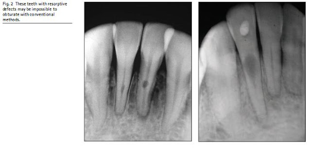
Nevertheless, the cold lateral compaction of gutta-percha is still the most widely taught, and the technique against which most others are compared. However, as there is a demand for saving teeth with complex pathology and root canal morphology (Fig. 2), it is sometimes easier to combine the merits of various techniques in a hybrid form to simplify the filling procedure. Studies have shown that these are satisfactory, although not always as easy as lateral compaction to carry out. 5,6

Wednesday, December 28, 2011

PROPERTIES OF ROOT CANAL FILLING MATERIALS

Ideally, a root canal filling should be:   Biocompatible
  Dimensionally stable   Capable of sealing the canal laterally and
apically, conforming with the various shapes and contours of the individual canal
  Unaffected by tissue fluids and insoluble   Bacteriostatic   Radiopaque   Easily removed from the canal if necessary.
To these properties may also be added, incapable of staining tooth or gingival tissues and easily manipulated with ample working time. Gutta-percha has a number of these desirable properties. It is semisolid and can be compressed and packed to fill the irregular shapes of a root canal using lateral or vertical compaction techniques. It is non-irritant and dimensionally stable. It will become plastic when heated or when used with solvents (xylol, chloroform, eucalyptus oil). It is radiopaque and inert, and can be removed from the canal when required for post preparation.

Its disadvantages are few. It is distorted by pressure and, consequently, can be forced through the apical foramen if too much pressure is used, and it is not rigid and so can be difficult to use in smaller sizes. Also, a sealer is necessary to fill in the spaces around the filling material. Root canal scalers were considered in Part 5.

Tuesday, December 27, 2011

Endodontics: Part 8 Filling the root canal system

In modern endodontic treatment the emphasis is placed far more on cleaning and preparing the root canal system than on filling it. This does not mean that root canal obturation is less important, but that the success of endodontic treatment depends on meticulous root canal preparation.
Endodontics: Part 8 Filling the root canal system

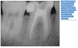
The purpose of a root canal filling, as illustrated in Figure 1, is to seal the root canal system to prevent: Microorganisms from entering and reinfecting the root canal system; Tissue fluids from percolating back into the root canal system and providing a culture medium for any residual bacteria.

REMOVAL OF SMEAR LAYER

A smear layer is created by the action of metallic instruments on dentine, especially rotary instruments. It is composed of dentine filings, pulpal tissue remnants and may also contain microbial elements. It may occlude dentine tubules thus harbouring bacteria, and may contain a bacterial plaque on the canal walls. It has been shown that gutta-percha penetrates the dentine tubules when the smear layer has been removed.
Fig. 2  These teeth with resorptive defects may be impossible to obturate with conventional methods.

It is therefore suggested that the root canal should be irrigated with an EDTA solution to remove the smear layer, followed by a final irrigation with sodium hypochlorite, prior to drying and obturating the canal.

Saturday, December 24, 2011

TEMPORARY RESTORATIVE MATERIALS

Fig. 16  A layer of gutta-percha temporary filling material has been placed to protect the root canals before the restorative material is applied. The inset shows how this may be removed and prevents fragments of the temporary filling entering the root canal.

If endodontic treatment cannot be completed in one visit, it is essential that a temporary restorative material is used as an inter-appointment dressing that will not permit access to bacteria or oral fluids. Even when the root canal treatment has been completed, a well-sealed temporary restoration is necessary prior to the placement of a permanent restoration. The material should prevent contamination of the root canal system and must be sufficiently strong to withstand the forces of mastication. Two different temporary materials are recommended. Of the many proprietary materials, Cavit has been shown to provide the best seal.
Cavit provides a good seal, is simple to apply and quick to set. On the other hand, it lacks strength and will not stand up to masticatory forces. It should be confined to single surface fillings for periods not exceeding a week. However, the shape of an endodontic access cavity is not retentive, and all such materials will either leak or be lost entirely in time. Any ingress of microorganisms may reinfect a prepared canal, and the time saved by using a rapid technique may be severely lost if such leakage occurs. Thus the use of a glass-ionomer cement should be considered. It is adhesive, antibacterial, stands up well to forces of mastication and is more stable than other materials. It is a useful routine, with an inter-appointment dressing, to place a sterile pledget of cotton wool in the pulp chamber, followed by a layer of gutta-percha. The temporary restorative material is then placed over the guttapercha (Fig. 16). At the next visit, a high-speed bur may be used to remove the temporary restoration without any danger of filling material lodging in the canal entrances or blocking the canals. The gutta-percha

Friday, December 23, 2011

Steroids

Fig. 15  Vitapex intracanal dressing
Steroids are readily obtainable in the form of triamcinalone (Ledermix paste). The use of the paste for dressing an inflamed vital pulp prior to commencing root canal therapy is discussed in Part 3. Some authorities recommend the use of the paste as an intervisit medicament paste when severe periradicular inflammation is present. It is suggested that it may be wiped on the canal wall using a file or paper point which is then withdrawn; a small amount is then placed
Fig. 15  Vitapex intracanal dressing.
on a pledget of cotton wool and sealed into the pulp chamber between appointments. The author prefers to mix the paste with a calcium hydroxide preparation, adding a little sterile water or local anaesthetic to make the mixture slightly more fluid. The canals may then be completely filled with this mixture prior to placing a temporary coronal seal. Of course, no

INTRACANAL MEDICATION Calcium hydroxide

Fig. 15  Vitapex intracanal dressing.
Calcium hydroxide There is almost universal agreement that when an intervisit dressing is required, calcium hydroxide is the material of choice, and this is discussed in Part 9. There is far less agreement as to whether such dressings are indicated. Singlevisit endodontics   the shaping, cleaning and obturation of the root canals in one appointment   remains controversial. Most endodontists would agree that when the tooth under treatment is not infected, for example when performing elective endodontics or treating large exposures of vital pulps, completing treatment in a single visit is advisable. However, Sj gren et al. showed a significant increase in prognosis when infected root canals were dressed with calcium hydroxide for one week before obturation.
Gutmann has suggested that this effect was only apparent because their research employed 1% sodium hypochlorite, whereas the use of a full strength solution would preclude the need for such a dressing.

The wise practitioner would consider which approach best suits his or her style of practice.
Calcium hydroxide is applied with a spiral paste filler (noting the caution given at Part 5, Fig. 20), or a fine-tipped syringe may be used as seen in Figure 14. Care should always be taken not to extrude the material beyond the apical constriction. If this happens, inflammation may result which could take several days to subside. Calcium hydroxide containing points are available from which it is postulated that ions will dissociate into the fluid in the root canal, and which may be better controlled in apical length. However, research supporting this has not yet been reported in the endodontic literature. 

Thursday, December 22, 2011

PATENCY FILING

Research has shown that most canal preparation techniques lead to the extrusion of debris through the apical foramen. This is removed by the normal body defence systems, although a certain amount of inflammation will result. Concern has been expressed by some authorities that such debris may remain in the apical constriction, and may contribute to failure, particularly if it harbours microorganisms.

The technique of patency filing involves passively inserting a small file, size 08 or 10, 2 mm beyond the established working length. No attempt is made to instrument the foramen, merely to keep it open or patent by deliberately extruding the debris into the periradicular tissues.

Wednesday, December 21, 2011

FURTHER READING


It must be stressed that the techniques described are generic, and that hands-on practice is essential, following the specific manufacturer s protocol until competence is achieved. The various instruments and techniques are described, compared and contrasted, in numerous publications, for example. The prudent clinician would be advised to refer to the endodontic literature before embarking on new purchases and clinical practice. A useful series of clinical articles was presented by Buchanan.

Tuesday, December 20, 2011

Summary of technique


  Motor set at slow speed recommended for instrument, usually 150 250 rpm.
  Use each instrument for only 5 10 seconds.   Light apical pressure, using either a gentle
 planing  pressure, or a slight  pecking  motion depending upon the instrument design.
  Use EDTA lubricant with each instrument.   Copious irrigation with sodium hypochlorite
between instruments.   Step down in sequence from the largest to the smallest. (NB This will depend upon which system is being used. If variable taper files have been selected, as in Fig. 5, then a 10% taper file will be used until resistance is felt, moving to an 8%, 6% and 4% until any of these reaches working length, depending upon the canal size. Alternatively, if a single taper, variable tip system has been selected, the largest tip size will be used first, reducing sizes as the canal is negotiated until, once

Apical preparation


Once the coronal preparation is completed, the canal should be explored to full working length using fine hand files and the balanced force technique. The working length should be confirmed, and the canal enlarged to a size 15 or 20. If this is not done, the rotary instrument will have to cut at its tip, rather than along its length, which may lead to jamming and fracture. Each time a file is removed from a canal after use the position of the dentine debris in the flutes should be inspected. The instruments should cut along their entire length. If debris is only seen at the tip, the instrument may be excessively stressed, which may lead to fracture. The apical part of the canal may now be prepared with sequentially smaller instruments, stepping down the canal with

Monday, December 19, 2011

Coronal preparation or radicular access


Nickel-titanium instruments cannot easily be precurved, and require straight line access to the root canal orifice. The use of ultrasonic tips to refine the access cavity has already been described. Nickel-titanium  orifice shapers  have replaced Gates-Glidden drills, and may be used sequentially from the largest to the smallest sizes. These remain centred in the canal and will flare the canal walls to approximately halfway down the canal. Their use may be restricted in narrow or curved canals. They are used with a very light apical pressure, often described as the  pencil-lead  pressure, ie that which would break the lead when using a propelling pencil. Each instrument should be used for no more than 5 10 seconds at a time before removing from the canal,

Saturday, December 17, 2011

NICKEL-TITANIUM ROTARY TECHNIQUE


The development and design of these instruments has been referred to earlier, and should be referred to in conjunction with this description of technique. Each manufacturer of these instruments produces a protocol for use for their own specific product. As it would not be appropriate to describe any single manufacturer s techniquehere, the description which follows must therefore be generic.

The basic concepts are the same whatever the instrument chosen. The technique for use is crown-down, with copious irrigation. Indeed, these instruments conform totally to the stated objectives in modern root canal therapy, shaping the canal rapidly and efficiently so that thorough cleaning of the root canal system can be carried out with appropriate irrigants. The files must be used in a slow-speed, controlled torque motor, or they

Friday, December 16, 2011

Stepback technique

Stepback течникуе, Following the preparation of the coronal part of the root canal, the apical preparation may also be carried out using the stepback technique. Starting with the size 15 file at the working length, and progressing to sizes 20 and 25, an apical stop is made. 
Copious irrigation and recapitulation with fine files will prevent build-up of canal debris. The master apical file will usually be no greater than 25 or 30. The apical portion of the canal is now tapered by stepping back. A file one size larger than the master apical file is worked with balanced force to 1.0 mm short of the working length. 

Thursday, December 15, 2011

Apical preparation

Apical preparation, The coronal flaring already carried out makes access to the apical portion of the root easier, as there are no dentinal obstructions and access is more direct. Thus, once the coronal preparation is complete, flexible K-type files with safe tips may be used sequentially with the balanced force technique previously described. A size appropriate to the particular canal and the final size Gates Glidden drill is selected, perhaps a size 60, 
Fig. 12  A diagrammatic illustration of the sequence of instruments in a conventional 2% taper hand file canal preparation.

the tip dipped into a canal lubricant, and the instrument worked slightly further into the canal. Sequentially smaller files are selected until the canal is prepared to 3 4 mm short of the estimated working length. Now the actual working length must be confirmed by one of the methods described earlier, radiograph or apex locator. Once the working length has been confirmed, the apical preparation can be completed. In narrow or

Wednesday, December 14, 2011

STEPDOWN TECHNIQUE WITH HAND FILES OF GREATER TAPER


The stepdown technique may be modified with the use of this range of files described by Buchanan in 1996. The balanced force technique is used as described previously, except that these instruments are used in the opposite rotation to conventional files. It was considered that the crucial part of the balanced force technique is the cutting cycle. Right-handed clinicians (representing some 90% of the work-force) can make this movement more easily in a clockwise direction than anticlockwise. Thus the initial movement to engage the dentine with these files only is a 60  turn anticlockwise, and the balanced force cutting motion is 360  clockwise.  
Following access to and irrigation of the pulp chamber the canal must first be gently explored to length with conventional 2% taper hand files. A gentle watchwinding technique is used with size 08, 10 and 15 files. The tip of the Greater Taper File then acts as a pathfinder rather than as a preparation file.  Using EDTA lubrication paste, the largest file with a blue handle and a taper of 12%, is used first to gain coronal access. When resistance is met the instrument is not forced further apically, but the red handled 10% taper file is used to penetrate further. The yellow handled 8% taper and white handled 6% taper follow in sequence, until the canal is prepared to working length.  The technique is varied according to the clinical situation. In a wide, straight canal, only a single 12% taper file may be required. In a narrow, curved canal, the

Coronal preparation or radicular access

Coronal preparation or radicular access, First, the pulp chamber is copiously irrigated with sodium hypochlorite. Gates Glidden burs are next introduced into the canal, directed apically and laterally away from the furcation. The larger sizes are introduced first, working sequentially further down the canal with smaller sizes. Some canals will accept a size 6 bur, but normally a size 4 would be used first, followed by a size 3. Each bur will penetrate 2 3 mm further than the previous one. EDTA paste should be used with each bur, and the canal should be irrigated between each entry. Eventually, in a relatively straight canal, the No. 2 bur is inserted 10 12 mm into the canal from the occlusal reference point. In a curved canal the pre-operative radiograph should be checked for the maximum straight line penetration of the bur.
Gates Glidden burs should be rotated with constant medium drill speed from the time they enter the canal until removed. Gates-Glidden burs must not be taken into a curve, or they will almost certainly fracture. If the shank of a bur does break, it usually does so near the handpiece head and may be retrieved easily from the tooth, as seen in Figure 11. However, if the head does become separated from the shank within the canal, removal may be extremely difficult.
The bur may be flexed against the canal wall slightly on withdrawal to ensure that the natural shape of the canal is maintained. Thus a round canal will remain round, but an oval canal will be prepared to a smooth oval funnel. A wide oval or  figure-of-eight  shape may need preparing at both extremities to produce a wide flare. Instrumentation with the stepdown technique in the radicular access is accomplished using only light pressure directed apically and away from the furcation, or perforation may result.
An alternative to Gates Glidden burs is the use of standard flexible K-type files with safe tips, used with the balanced force technique. Following initial widening of the mouth of the canal only with a Gates Glidden bur, the largest hand file which will enter the canal is selected and worked apically, using

Tuesday, December 13, 2011

PREPARATION OF THE ROOT CANAL

PREPARATION OF THE ROOT CANAL
Two techniques will be presented in detail, one using conventional hand instrumentation and one using nickel-titanium hand Files of Greater Taper. The stepdown technique has been modified slightly from the original description by Goerig.

STEPDOWN TECHNIQUE WITH CONVENTIONAL 2% TAPER INSTRUMENTS

STEP DOWN TECHNIQUE WITH CONVENTIONAL 2% TAPER INSTRUMENTS
A preoperative radiograph is taken, rubber dam placed and an access cavity prepared. The canal preparation is divided into two parts: i) coronal preparation, which permits radicular access for ii) apical instrumentation.

Tactile sensation

Tactile sensation

An experienced clinician, armed with an accurate preoperative parallel radiograph, can often feel the apical constriction with a fine instrument. If tactile sensation is in accord with the estimated length, further confirmation may not be necessary.

Working length radiograph

Working length radiograph, A file is placed carefully in the canal until it is within approximately 2.0 mm of the overall length. Before insertion the file should be precurved to the shape of the canal and gently manoeuvred into position, if necessary using a watchwinding technique and slight apical pressure. For accurate reading of the radiograph a size 15 file is usually necessary. 
Working length radiograph

A silicone stop on the instrument shank is positioned against a reference point on the tooth, and both the length and the reference point should be noted in the records. When taking diagnostic radiographs, use should be made of the  buccal object rule , where there are two or more canals present in the root (Figs 9 and 10). A second way of achieving the same result is to place a Hedstroem file in one canal and a K-file in the other, as the difference between the two is clear on the radiograph. The working length is calculated by measuring directly on the radiograph from the tip of the instrument to 1.0 mm short of the radiographic apex. It is only possible to

Monday, December 12, 2011

DETERMINATION OF ROOT CANAL LENGTH

DETERMINATION OF ROOT CANAL LENGTH
The exact apical termination of the root canal preparation has always been a subject of contention. The pedantic answer is that the root canal should be prepared to that point where the  inside  of the tooth becomes the  outside . Some authors suggest this is the apical constriction, some the cemento-dentinal junction, some suggest that the apical foramen should be enlarged, some suggest that the preparation be taken to an arbitrary point 1 mm from the radiographic apex. As described in Part 4, the apical anatomy may be complex, and the term apical delta may be more appropriate. This author considers that the preparation should be taken as close as possible to the cemento-dentinal junction, and that wherever possible the foramen of the major canal should be kept patent. (This technique is described later.) The other minor canals forming the apical delta will only be cleaned by antibacterial irrigation flushing through the entire canal system.
An estimate of the root length is made from the pre-operative radiograph taken with a parallel technique. However, confirmation of the actual working length is not carried out until the coronal preparation of the canal has been completed, as this may straighten a curved canal which would change a measurement that had been taken too early. Most operators now confirm the

LUBRICATION

LUBRICATION
Proprietory pastes containing EDTA are available, in combination with various agents, which greatly help instrumentation by chelating and softening the dentine. If a small portion is dispensed near to the file storage system, a little may be picked up on the tip of each new file as it is selected .

Ethylene-diamene tetracetic acid (EDTA) solution

Ethylene-diamene tetracetic acid (EDTA) solution
Endodontic instrumentation creates a smear layer on the root canal walls, particularly when using nickel-titanium rotary instruments. This smear layer occludes the dentinal tubules, and may protect microorganisms from the effects of the sodium hypochlorite irrigation. Flushing the canal with EDTA solution (Fig. 7) periodically during instrumentation removes the smear layer, and enables more effective cleansing. The final irrigation should always be with sodium hypochlorite.

Chlorhexidine


As referred to in Part 5, some practitioners have concerns about the use of sodium hypochlorite and prefer to use a solution of chlorhexidine. Whilst this has a similar antibacterial spectrum, it does not have the ability to dissolve organic debris and may not clean the entire root canal system as effectively. However, chlorhexidine does exhibit substantivity (adherence to dentine) and there is some evidence to suggest that it may be a more appropriate irrigant for retreatment of failed orthograde cases where sodium hypochlorite was the original irrigant.

Electronic apex locators


Electronic apex locators (seen in Part 5) may be used as an alternative to a workinglength radiograph, assuming that a pre-operative film has been examined to obtain an estimated figure. These machines are capable of accurate measurement, and will give the location of the apical foramen. Apex locators are essential when a patient elects to have a minimum number of further radiographs taken. Many practitioners now use them routinely, particularly when the outline of the canal on the pre-operative film is indistinct or the canal curves towards or away from the radiograph beam. Modern apex locators work using different frequencies, determining the ratio between the different electric potentials proportional to each impedance. There is no longer any need to
dry the canal before use as they work in the presence of electrolytes. There is a distinct learning curve with their use, but it is usually apparent whether or not the measurement is in accordance with the original radiographic estimated working length. Errors may occur if there is a large coronal restoration or metallic crown causing a short circuit; if there is an open apex with a large periradicular lesion, or if there is a perforation. These are usually apparent and further measures should be taken. In use, a file is inserted into the root canal and an electrical contact is made with the shank of the instrument. The device has a second electrode, which is placed in contact with the patient s oral mucosa. A digital display or audible signal shows when the tip of the instrument reaches the apical foramen. There is no

Sunday, December 11, 2011

IRRIGATION Sodium hypochlorite

IRRIGATION Sodium hypochlorite
The importance of effective irrigation in root canal preparation cannot be overemphasised. A maxim in endodontics states that it is what you take out of a root canal that is important, not what you put in. Sodium hypochlorite is considered the most effective irrigant, as it is bactericidal, dissolves organic debris and is only a mild irritant. It must be clearly understood that almost any irrigant solution will cause an inflammatory reaction in the periapical tissues if it is expressed under pressure.Great care must be taken to follow the irrigation regime described below. There is considerable debate about the recommended or optimum concentration of sodium hypochlorite. Ordinary domestic bleach, such as that purchased from any supermarket, has approximately 5% available chlorine. This may be used neat, or may be diluted with purified water BP up to 5 times. Greater dilutions do not affect the antibacterial properties, but diminish the tissue dissolution property.  Diluted solutions must therefore remain in the root canal for longer. Warming the irrigant makes it even more effective.

Nickel-titanium


However, the development of nickel-titanium alloys has revolutionised automated root canal preparation. The remarkable ability of these alloys to alter their crystalline state gives instruments manufactured from nickel-titanium profound flexibility. Mechanised instruments can withstand the distortions caused by repeated rotation in curved canals without causing preparation errors. Most of these instruments have design features such as radial lands (Fig. 4) to keep the instrument centred in the canal, and a non-cutting tip to guide the instrument down the canal. New designs are constantly appearing, (Fig. 5) and the clinician should ensure that considerable experience with whichever system is chosen has been obtained on extracted teeth, before the instruments are introduced into clinical patient treatment.
A controlled high-torque, low-speed motor is required for efficient use of the instruments. Most manufacturers of endodontic instruments produce such a motor, and their complexity may vary from that illustrated in Part 5, Figure 12, to that shown here in Figure 6. It must be emphasized that these nickel-titanium instruments do have a limited life, and will fracture in time after a large number of rotations. Slow (150 250 rpm) rotation does not impede their efficiency but extends their life. However, it is recommended that the instruments should be discarded after a certain number of cases as described by the
Fig. 5  One modern system of nickel-titanium rotary instruments   the System GT.
Fig. 6  A  state-of-the-art  endodontic motor

Saturday, December 10, 2011

Automated devices

There have been many automated handpieces on the market over the years which claim to make the preparation of root canals quicker and more efficient. Although different designs and mechanical actions have been tried, they have all suffered from the inherent difficulties referred to earlier, caused by rotating or twisting conventional stainless steel instruments, such as zipping, perforation, canal transportation and broken instruments.

Friday, December 9, 2011

Ultrasonic technique

Fig. 3  The root canal in this tooth contains necrotic infected debris. The objective in endodontics is to remove the debris without extruding any through the apical foramen.  It makes good sense to use a technique which cleans the coronal part first and then the apical portion.
Ultrasound has been used to activate specially designed endodontic files. Ultrasound consists of acoustic waves which have a frequency higher than can be perceived by a human ear. The acoustic energy is transmitted to the root canal instrument, which oscillates at 20 40,000 cycles per second, depending on which unit is used. The superior cleaning effect is achieved by acoustic streaming of the irrigant and not, as originally thought, by cavitation. Irrigation with sodium hypochlorite is necessary, although some of the ultrasonic units are not designed to accept sodium hypochlorite through the system and, if water is used, they will be less efficient in their cleansing effect. Even when units designed to take sodium hypochlorite are used, daily maintenance must be carried out to prevent damage, particularly to metals, because the irrigant is corrosive.

Wednesday, December 7, 2011

The balanced force technique

The balanced force technique, first described by Roane et al.,is now the most widely taught technique for manipulating handfiles. It is particularly good when negotiating the curved root canal. The technique requires flexible files with non-cutting tips. The file is inserted into the canal until slight resistance is felt and then rotated 60  clockwise to engage the flutes into the dentine. If a greater movement is made, iatrogenic problems can quickly arise. Using light apical finger pressure to hold the file at exactly the same depth in the canal, the file is now rotated through 360  in an anticlockwise direction. The first 60  of this turn cuts off the dentine engaged in the flutes of the file, and the remainder of the movement picks up this dentine in the flutes of the file prior to the next cycle. The amount of apical pressure required to rotate the file anticlockwise is just sufficient to prevent it from winding out of the canal. Watching the rubber stop in relation to the tooth assists in keeping the file steady with no in or out movement. 

Tuesday, December 6, 2011

INSTRUMENT MANIPULATION Watchwinding and circumferential filing

In addition to the method of approach to the root canal, there have been numerous techniques for the manipulation of endodontic shaping instruments.
Watchwinding and circumferential filing
Watchwinding, or a continuous back and forth rotation with slight apical pressure, rapidly advances a fine file down a root canal. Each slight turn engages the flutes of the file in the canal wall and removes dentine. Only fine files should be advanced to the apex in this way as there is a danger of compacting pulpal debris ahead of the file. If such a blockage occurs it can be extremely difficult to remove.
Once the file has reached the desired length, a push-pull filing action was used, moving the file circumferentially around the canal walls. When using K-type files an attempt was made to file on the outstroke only, again to reduce the apical compaction of debris. Hedstroem files were more efficient for circumferential filing, although these should not be used when watchwinding. Research into canal preparation found two distinct problems with circumferential filing. 
The first was a tendency to preferentially file the inside wall of a curved canal. The technique of anticurvature filing was put forward by Abou-Rass et al. Anticurvature filing involves filing predominantly away from the inner curve of a root to reduce the risk of a strip perforation. The mesiobuccal roots of maxillary molars and the mesial roots of mandibular molars are the teeth most frequently at risk. The method is used only in canals with a moderate-to-severe curve.  

Stepdown technique

Fig. 3  The root canal in this tooth contains necrotic infected debris. The objective in endodontics is to remove the debris without extruding any through the apical foramen.  It makes good sense to use a technique which cleans the coronal part first and then the apical portion

This method, although not the term stepdown, was first suggested by Schilder in 1974, and the technique was described in detail by Goerig et al.2
It has been followed by other, similar techniques such as the double flared3
and the crown-down pressureless.4
The principle of these techniques is that the coronal aspect of the root canal is widened and cleaned before the apical part (Fig. 3). The obvious advantages of these methods over the stepback are as follows.
  It permits straighter access to the apical region of the root canal.
  It eliminates dentinal interferences found in the coronal two-thirds of the canal, allowing apical instrumentation to be accomplished quickly and efficiently.

DEVELOPMENT OF PREPARATION TECHNIQUES

In order to fully understand the current techniques for canal preparation, it would be beneficial to look briefly at previous methods, and the associated problems which led to further development. Interestingly, in 1933 a paper was published in the dental literature recommending the use of maggots to consume and remove the necrotic larger instrument is then inserted 1.0 mm less into the canal so that a taper is formed. In between placing each larger instrument, the master apical file is inserted to the working length to clear any debris collecting in the apical part of the canal; this is referred to as recapitulation. The stepback technique helped to overcome the procedural errors of the standardised technique in slight to moderately curved canals, but in the more severely curved root canals problems still exist. There are three ways in which some of the problems of the curved root canal may be overcome, by using:

Monday, December 5, 2011

PRINCIPLES AND RECENT DEVELOPMENTS OF ROOT CANAL PREPARATION

Fig. 1  The shape of the prepared root canal should be a gradual, even taper, with the widest part coronally and the narrowest part 1.0 mm from the root apex.
The principles of root canal preparation are to remove all organic debris and microorganisms from the root canal system, and to shape the walls of the root canal to facilitate that cleaning and the subsequent obturation of the entire root canal space. However, a tooth root rarely contains a single simple root canal. Accessory canals, lateral canals, fins, anastomoses between canals, and an apical delta all contribute to the root canal system, as shown in Part 1. The majority of these anatomical features are not accessible to instrumentation. An irrigant solution must be used which can be flushed through this system, will destroy the microorganisms and preferably dissolve organic debris at the same time. Thus the current concept of root canal preparation is not cleaning and shaping, but shaping and cleaning. The main root canals should be rapidly and efficiently shaped with instruments to permit thorough and extended cleaning of the entire pulpal system with the irrigant solution. Once shaped and cleaned, the root canal system is obturated to prevent further ingress of microorganisms, both apically and coronally, and to entomb any remaining microorganisms to prevent their proliferation. Currently, the root canal filling material of choice is gutta-percha, which requires a gradual, even, funnel-

ACCESS Access cavity preparation

There is an old clichØ that  Access is Success . Unlike other aspects of dentistry, root canal treatment is carried out with little visual guidance; therefore, the difficulties that are likely to be encountered need to be considered. An assessment of the following features can be made after visual examination of the tooth, and study of a pre-operative periapical radiograph taken with a paralleling technique:
  The external morphology of the tooth.   The architecture of the tooth s root canal
system.   The number of canals present.   The length, direction and degree of curvature
of each canal.   Any branching or division of the main canals.   The relationship of the canal orifice(s) to the pulp chamber and to the external surface of the tooth.
  The presence and location of any lateral canals.
  The position and size of the pulp chamber and its distance from the occlusal surface.
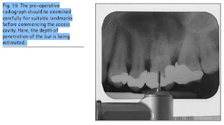
Fig. 19  The pre-operative radiograph should be examined carefully for suitable landmarks before commencing the access cavity. Here, the depth of penetration of the bur is being estimated.

  Any related pathology.
Before commencement of root canal treatment, the tooth must be prepared as follows:
  All caries and any defective restorations should be removed and made good. The tooth should be protected against fracture during treatment.
  The tooth should be capable of isolation.   The periodontal status should be sound, orcapable of resolution. It may be prudent to commence access cavity
preparation before isolating the tooth with rubber dam in order that the anatomical landmarks, tooth inclination and other helpful features are not lost. It is, of course, crucial that the root canal does not become contaminated during either access preparation or canal instrumentation, and the tooth should be isolated in an aseptic field as soon as possible.
If there is a danger of fracture of the coronal tooth structure, the cuspal height should be reduced to prevent this. If the loss of coronal tissue is extensive, there may be a need to provisionally restore the tooth with a temporary crown, copper ring or an orthodontic band. It is, however, not always necessary to restore the tooth before carrying out endodontic procedures. Provided the tooth will anchor a rubber dam, the canals can be isolated from the oral cavity and a temporary seal can be placed over the canals, this will be sufficient.
The objectives of access cavity preparation are to:
  Remove the entire roof of the pulp chamber so that the pulp chamber can be debrided.
  Enable the root canals to be located and instrumented by providing direct straight line access to the apical third of the root canals, as illustrated in Figure 6.17. Note that the initial access cavity may have to be modified during treatment to achieve this.
  Enable a temporary seal to be placed securely in order to withstand any displacing forces.
  Conserve as much sound tooth tissue as possible and as is consistent with treatment objectives.
The subsequent restoration of the tooth should always be considered first. If the tooth is not heavily restored then only the amount of coronal tissue sufficient for the successful completion of the root canal treatment should beremoved. However, if the tooth is already compromised and will require some form of cuspal coverage restoration, an onlay or a crown, then it may be practical to reduce the cusp height, particularly mesiobuccally in molars, to enable better visualisation of the pulp chamber. If access to the back of the mouth is difficult, it is again reasonable to consider reducing the marginal ridge of the tooth concerned to achieve this (Fig. 18), or perhaps gain access through the mesiobuccal wall. Unless the root treatment is successful, any further restoration to the tooth will be put at risk.

Bridges

Bridges do not present a problem with the application of rubber dam. A suitable winged clamp is fitted onto the abutment tooth and the dam stretched over the clamp. If there are any small gaps, these can be sealed with a caulking material such as Oraseal or Cavit.
When root treating teeth acting as bridge abutments a careful check should always be made that the bridge is not loose. If a bridge has become debonded it must be removed. This should be carried out before any attempt is made to root-treat one of the abutment teeth.


DIFFICULT SITUATIONS The broken down tooth

There are a few situations where the application of rubber dam may present difficulties, although the cautious clinician may consider whether root canal treatment is then either appropriate, or may be severely compromised.
The broken down tooth
The broken down tooth may be tackled in a variety of ways. Many molar teeth with large deficiencies may have rubber dam applied, providing the right clamp is used; the author recommends a W8a (see Fig. 2). With an appropriate length of floss as described earlier, the clamp is placed directly on to the tooth, so that there is a four-point contact between the jaws of clamp and the root. Once in position, the clamp is checked for stability by pressing on the bow. If firm, the rubber dam may be stretched over the clamp using the wingless technique described.

Sunday, December 4, 2011

Everting the margins

If the rubber dam is lying on the tooth surface it may allow leakage of saliva, a problem particularly when the dam has been applied during adhesive restorative procedures, but also with endodontics. The margin should be everted into the gingival crevice as shown in Figure 14.

The operator stretches the rubber away from the tooth whilst the assistant directs a stream of cold air from the triple syringe onto the mucosa. With the use of a flat plastic instrument the margin of the rubber dam may be tucked into the gingival crevice, providing a tight seal.

Friday, December 2, 2011

Anterior teeth


As stated previously, in a relatively intact arch it is easier to isolate several anterior teeth. Dental floss should be used first to verify that the contacts are clear and that the rubber dam will pass through. The rubber sheet is held against the teeth and the centre point marked of those teeth to be isolated. Holes are punched at these points, and the rubber dam is then applied to the teeth. Taking a leading edge of rubber through the contact    knifing through    makes application relatively simple, or dental floss may be used to draw the rubber through a difficult contact. Once in place the selected wedges are applied.

Thursday, December 1, 2011

Rubber first

Fig. 13  The rubber first method. The operator is holding the sheet over the tooth whilst the assistant places the clamp to secure it in place.

The third method taught in some centres involves the dental nurse to a greater extent. The dentist stretches out the rubber and places the hole over the tooth in question, holding it down on each side with light finger pressure. At the same time the dental nurse picks up the flossed clamp in the forceps and places it over the tooth, retaining the dam in place (Fig. 13). Once again, the frame and

Wingless technique

The appropriate wingless clamp (W8A for molars, W1 for premolars) is selected and flossed. The rubber dam is punched and aligned with the quadrant to be treated. The clamp, held in the forceps and retained with the ratchet, is placed securely on the tooth. One advantage of this method is that the opportunity now exists to verify the fit of the clamp before proceeding (Fig. 12).
Fig. 12  The wingless technique.  a) The flossed clamp has been placed on the tooth, and b) the rubber is stretched over the bow and pulled forward around the clamp.

The rubber dam is now held in both hands, and the index fingers used to stretch out the punched hole, which is slipped over the bow of the clamp and pulled forward and down onto the tooth. Again, the nurse may hold the top of the sheet to improve vision for the operator. The frame and

Wednesday, November 30, 2011

APPLICATION TECHNIQUES Winged technique

Fig. 11  The winged technique. The hole in the rubber sheet has been stretched over the wings of the clamp a), which is then fitted to the tooth b). The rubber is pushed off the wings, and the seal verified.
A well-trained dental nurse and a well organised surgery, are essential for efficient application of the rubber dam. If a tray is prepared with ready punched sheets, and sterilised clamps already flossed, application can be performed in a matter of seconds.
There are three standard methods of application, described and illustrated here.


Winged technique
The appropriate winged clamp (8A for molars, 1 for premolars) is selected and flossed. The rubber dam is punched and aligned with the quadrant to be treated. The clamp is held in the forceps and retained with the ratchet. The hole in the rubber is stretched across the wings of the clamp, positioning the bow of the clamp towards the back of the arch. All this may be done by the dental nurse while the dentist is otherwise occupied,

The rubber dam frame

Fig. 10  The rubber dam frame may be easier to place beneath the rubber sheet.

The old Ash frame, with its  butterfly  retainers, has largely been replaced by plastic or metal frames with sharp points or pins. It should be noted that the majority of these retentive points slope backwards, and the frames are designed to be placed under the rubber dam (Fig. 10). It seems to be much easier to place the frame beneath the dam and simply stretch the sheet over the points than the other way round. In addition, the tension in the sheet can be better controlled, particularly relevant when working in a situation where the clamp may be less retentive than normal.

Endodontics: Part 7 Preparing the root canal

Success in endodontic treatment depends almost completely on how well the root canal is shaped and cleaned. This part will cover the principles of root canal preparation, irrigation, root length determination, intracanal medication, and temporary fillings.
There have been more developments in recent years in this aspect of endodontic practice than any other. New instruments have been developed, employing different metals and different engineering philosophies. There has been a significant move away from the ISO standard 2% taper instrumentation.

Rubber dam forceps

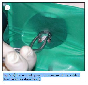
Fig. 5  a) The second groove for removal of the rubber dam clamp, as shown in b).


The rubber dam forceps are used to carry the clamp to the tooth. The most frequently reported problem with rubber dam is that when the clamp has been expanded and placed on the tooth, the forceps are stuck in the clamp and cannot be removed! This is because the grooves in the tips of the forceps are too deep. These should be modified with a stone or sandpaper disc so that they just engage the clamp, but slide off easily. Most forceps have a second groove slightly distant from the tip, which may be used to remove the rubber dam clamp without re-engaging the holes (Figs 4 and 5).

Split dam

Occasionally, a broken down tooth may be isolated using a slit cut between the holes made for the two adjacent teeth, as shown in Figure 16. It is essential that the caulking material illustrated in Figure 9 is applied to prevent leakage and contamination.

Finally, if an operator decides to proceed with root canal treatment without the use of rubber dam, each hand file must be protected with either floss tied around the handle or an appropriate safety device. The excess saliva must be controlled with cotton wool rolls and aspiration, and great care must be taken with medicaments. It would be advisable to inform the patient of the risks involved, and the reduced prognosis for the treatment if

Rubber dam clamps

There is a vast range of shapes and sizes of rubber dam clamps, supposedly to suit every possible tooth and situation. In fact, this merely causes confusion, as an ill-fitting clamp may be quite unsatisfactory, and dislodge during treatment. When properly fitted, a clamp should have four point contact with the tooth. If not, it will either rock back and forward or dislodge completely.
Fig. 9  a) A caulking agent which may be used to seal voids around the rubber dam that may allow salivary contamination, as shown in b).

Clamps are described as being either  active , where the jaws slope downwards and positively slide into cervical undercuts, or  passive  when they tend to remain where placed. They may also be either winged or wingless, depending upon the chosen method of application.
The size 8A clamp is described by the manufacturers as a  universal retentive molar clamp .It is an active clamp, and fits every molar tooth, even when these are quite broken down. The author would suggest therefore that all the other designs merely confuse the issue, and until the operator is very experienced only this clamp is used for all molar teeth. Likewise, the size 1 fits virtually all premolars (Fig. 6). If passive clamps are preferred size 0 or 00 are suitable for premolars, although they will not be as retentive. Rather than place aggressive clamps on anterior teeth, it is usually kinder to use interproximal wedges, either pieces of rubber dam or a commercial product such as  Wedgets  (Fig. 7). It is often easier to isolate several anterior teeth, giving a clear operating field.

Rubber dam stamp

Fig. 3  For multiple isolation, the position of the holes to be punched may be marked by holding the rubber dam against the teeth.

This is another piece of equipment now largely superseded. For single tooth isolation, a hole punched 2 cm diagonally from the middle of the sheet gives universal dam. The hole is simply orientated to the quadrant under treatment. For multiple isolation, it is preferable to hold the dam against the teeth to be isolated, and mark the centre of each tooth with a pen, as shown in Figure 3. The holes will then be punched in accordance with the patient s dentition and not with an arbitrary stamp. 

Tuesday, November 29, 2011

Rubber dam punch


Fig. 3  For multiple isolation, the position of the holes to be punched may be marked by holding the rubber dam against the teeth.
Much of the equipment for rubber dam has been rationally modified. The revolving plate on the old punch was rarely used, as a single size hole will really fit all teeth. When the table was moved it frequently led to eccentric wear of the pin, which then did not cut a clean hole. The defect in the cut may cause the dam to split when stretched out. The new rubber dam punches are single table (Fig. 2) and should always cut a clean hole.

Wednesday, October 5, 2011

Rubber dam sheets

Most manufacturers supply rubber dam in three thicknesses or grades, for different applications. Depending upon the manufacturer, these will be designated either light, medium and heavy, or medium, heavy and extra-heavy. The thinnest of the three is more prone to splitting, and the heaviest more difficult to manipulate, which means that the most widely used is the middle grade. The sheets are presented in a variety of colours, some being impregnated with peppermint and other scents to disguise the smell of the rubber. The feel of rubber against the skin may be countered by simply placing a gauze underneath the dam.

Endodontics: Part 6 Rubber dam and access cavities

Endodontics: Part 6 Rubber dam and access cavities
RUBBER DAM
The use of a rubber dam is almost mandatory in modern endodontic practice for three reasons.
Firstly, it provides an aseptic operating field, isolating the tooth from oral and salivary contamination. It cannot be stressed enough that contamination of the root canal with saliva introduces new microorganisms to the root canal which may prolong treatment and reduce prognosis.
Secondly, rubber dam facilitates the use of the strong medicaments necessary to clean the root canal system.
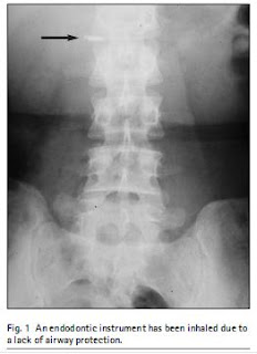
Finally, it protects the patient from the inhalation or ingestion of endodontic instruments, as shown in Figure 1.
Practitioners may also be advised to develop their rubber dam skills for another reason. Research has shown

that rubber dam used during routine conservation procedures reduces aerosol contamination and cross-infection by up to 98.5%.
Research has also shown that patients do not dislike the use of rubber dam,